• Welcome to For Trucks Only !

    We are a community of American Brand Pickup Truck and SUV owners. Join now! Its Free!

My Father & Son Dodge Truck build.

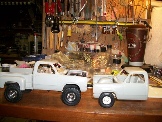
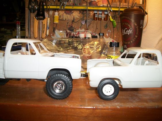
SO, with the weather being NIICE out its been difficult getting "A LOT" done on any modeling but I did manage a little bit.....
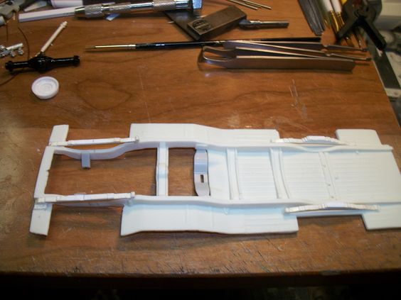
I got to looking at that old Donor frame, that I'm trying to save as its styrene for my Railroad truck build as I'll be doing extensive frame work to it for that model, BUT I was more interested in the suspension to go under my Dads '79 Adventurer 150...... SO, I seen that the crude steering details they at MPC made way back when, it was good for the time back then, BUT, I thought I could improve upon it....
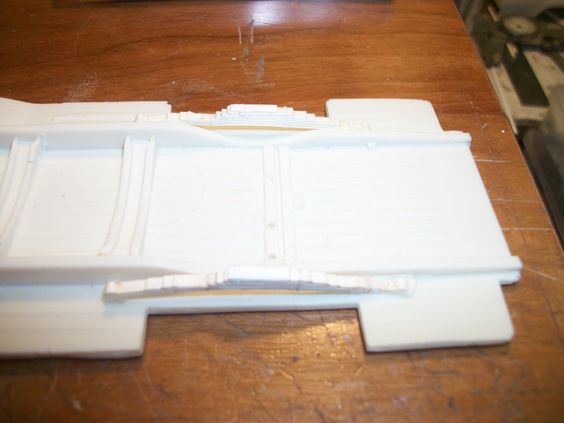
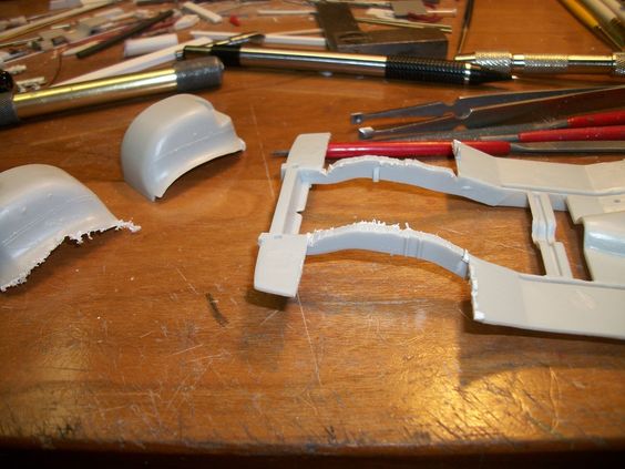
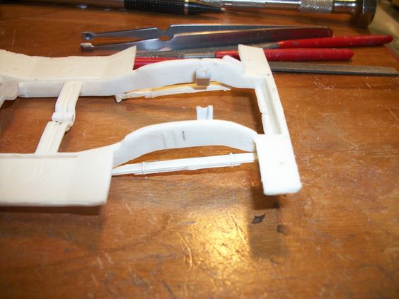
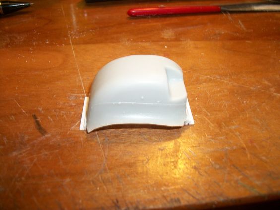
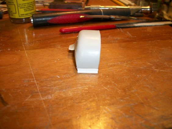
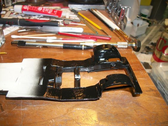
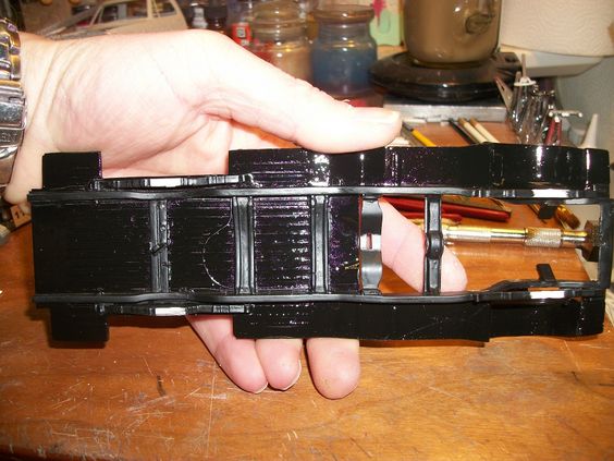
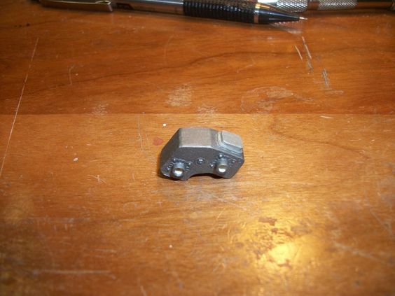
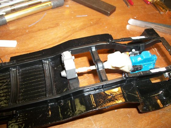
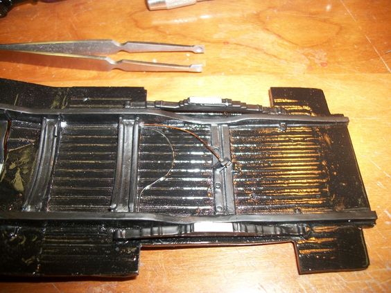
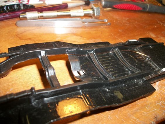
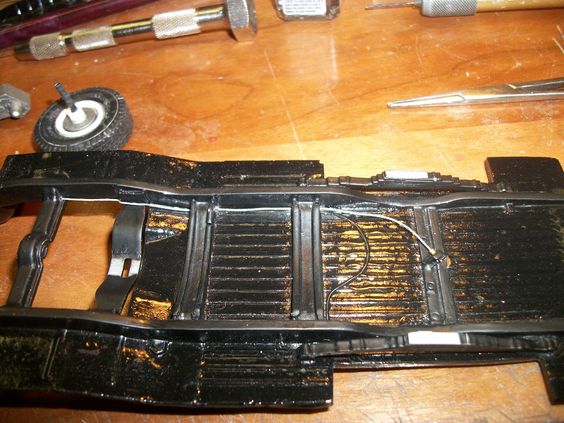
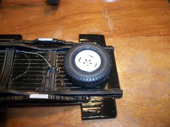
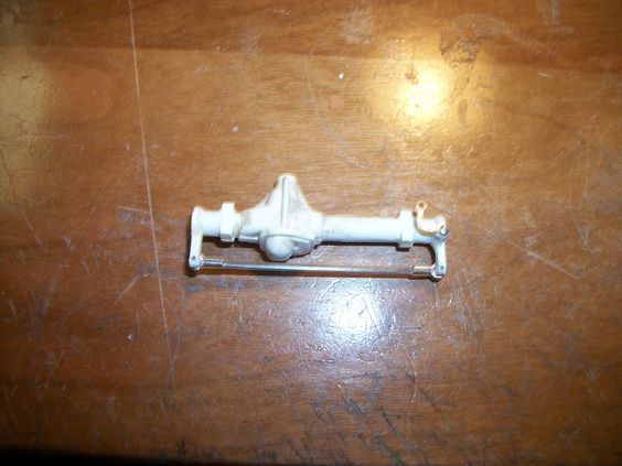
Went from this:
95e90df0e9db9d50214d2a1fef208815.jpg

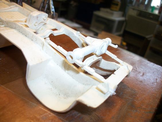
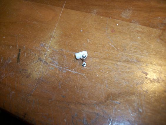
Removed from the styrene frame.....
61b0476ffd4f2ed3d0886bef7968424c.jpg

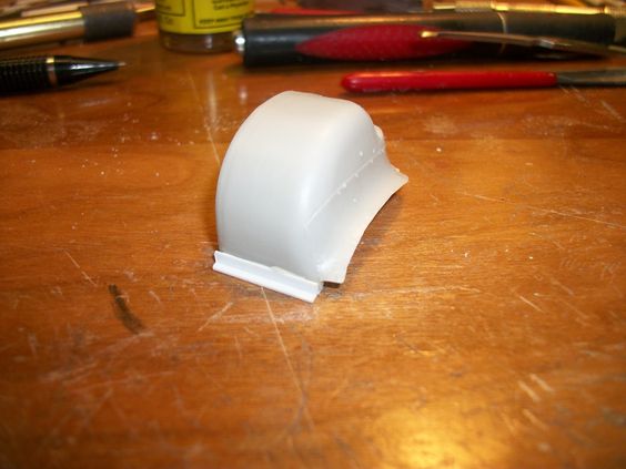
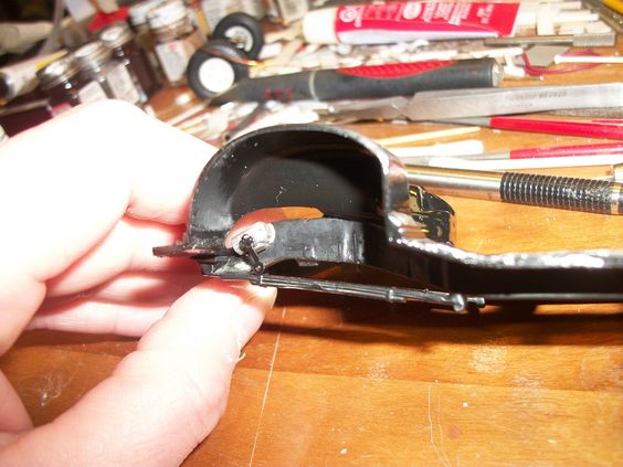
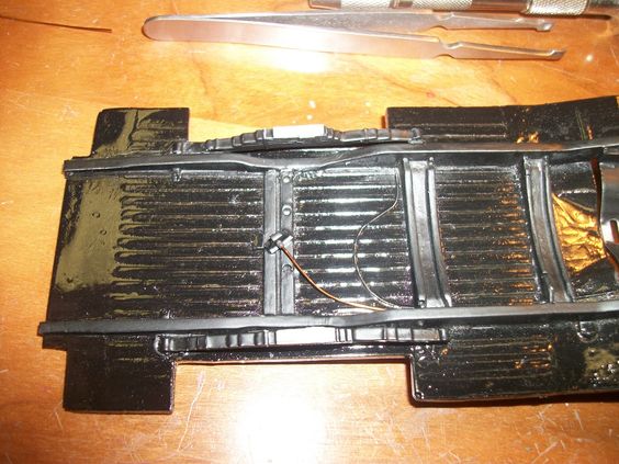
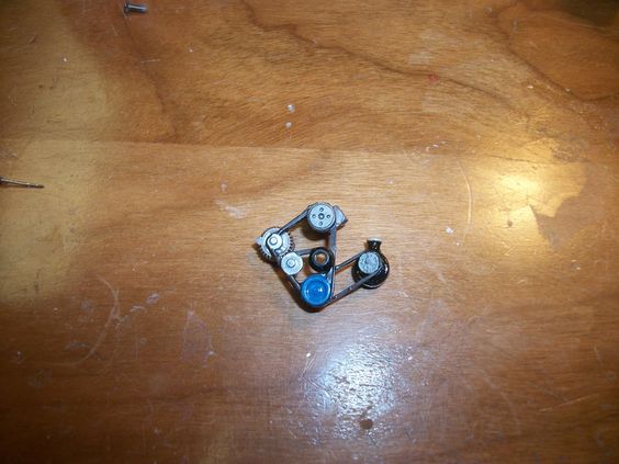
Better view as the part itself. I think that steering tie-rod, could be improved in detailing so, I went on to do a bit more then just replace the missing "rod" MPC had originally with the part.
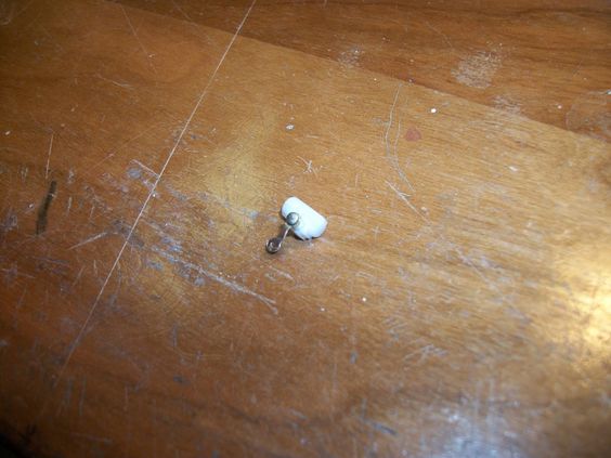
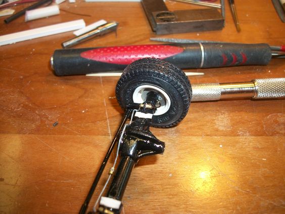
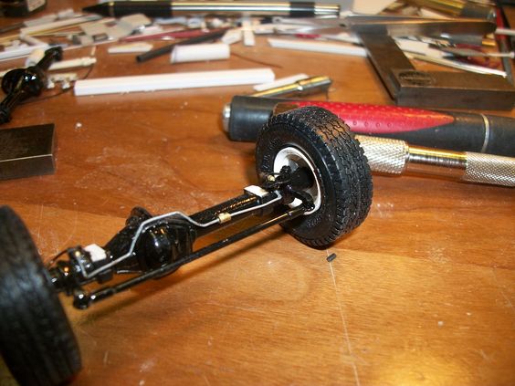
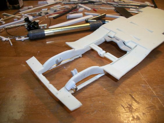
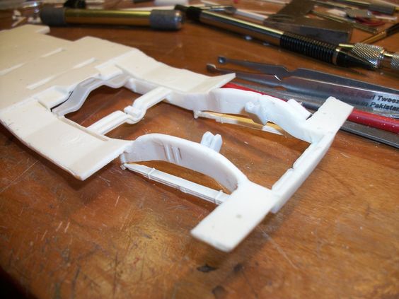
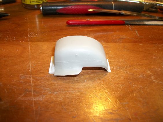
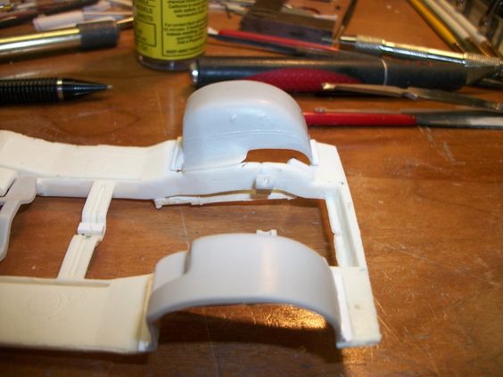
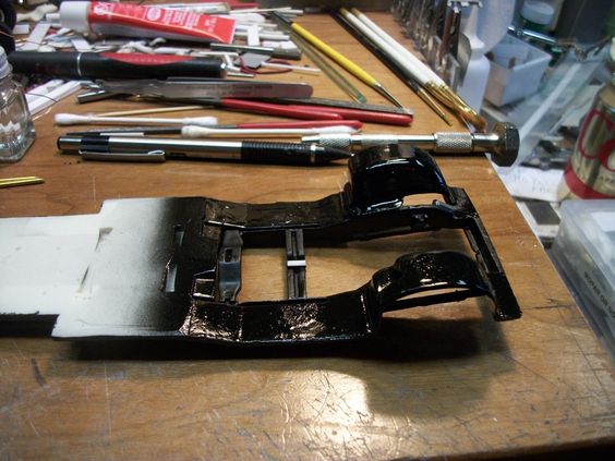
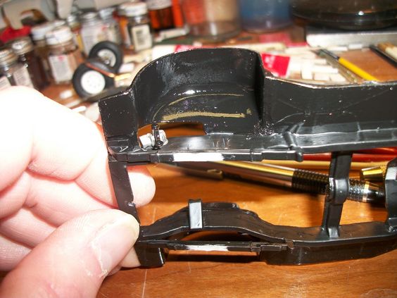
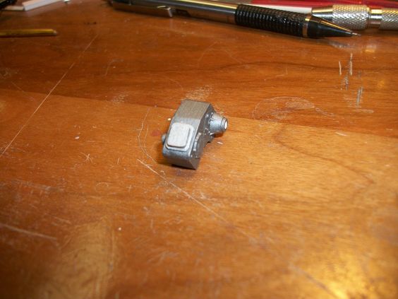
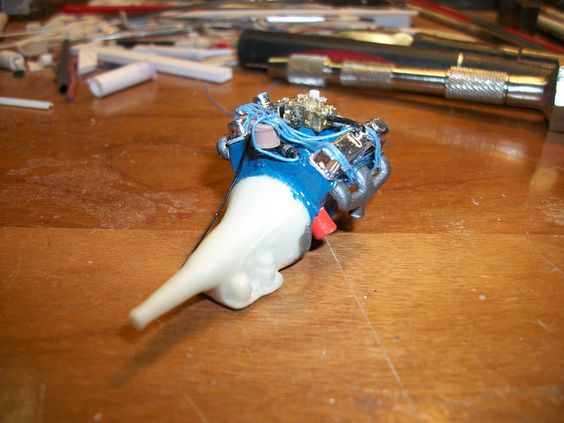
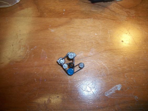
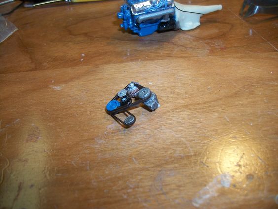
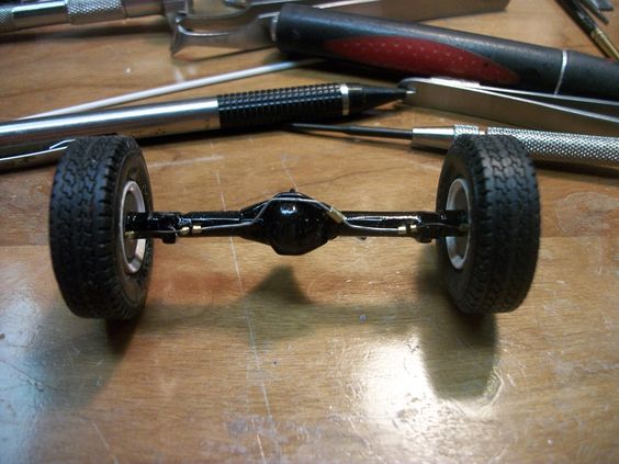
Heres what I made it to be:
b09d26f4971dff569da1b15284c41770.jpg

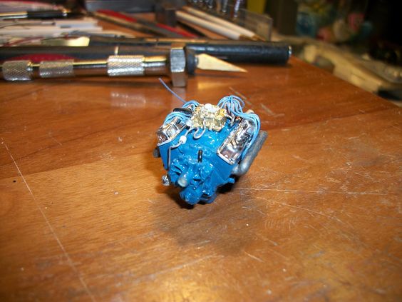
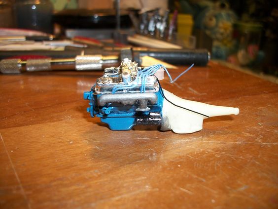
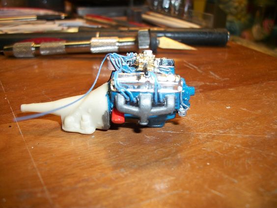
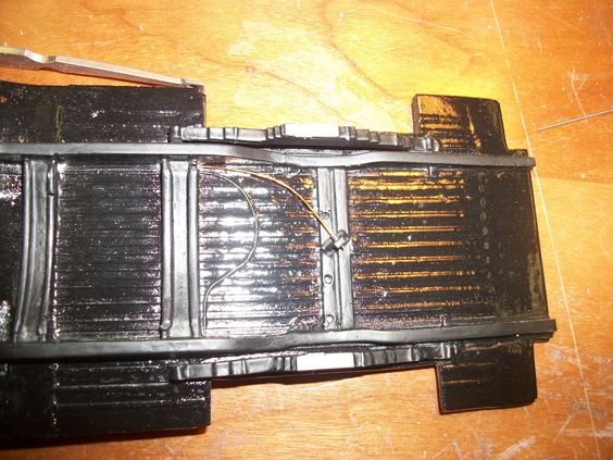
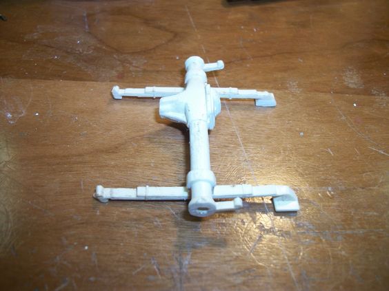
Right side up, removed from the leaf springs, for detailing and height adjustment. I also added the drag link that would connect to anther rod that goes to the power steering, this detail wasn't even one the model, I made it myself, and added it from pictures of a real Dodge Adventurer truck! -It is a bit different from what I had in my Power Wagon! I knew there would be differences, BUT I tell you all, theres a bit more building these 2 trucks then I ever thought in the beginning, more then just the exterior, and interior...... AND even the motors!
6850d2eb640c1f7484bff4831a5f3678.jpg

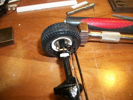
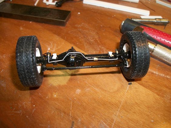
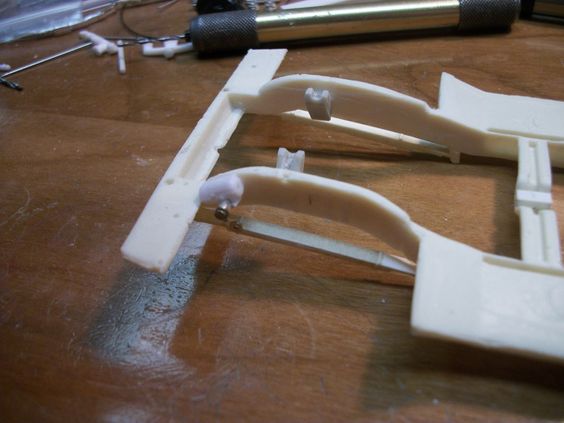
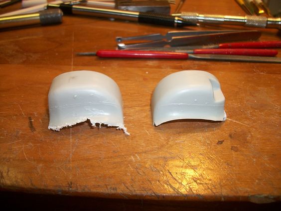
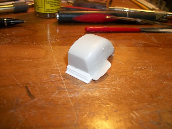
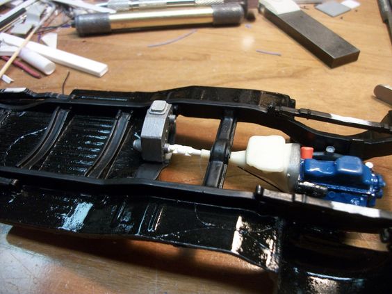
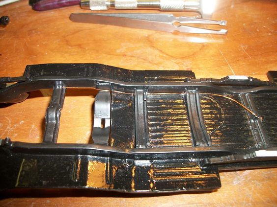
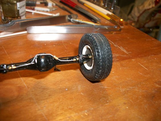
Notice, I removed a bit out of the mount where the rear mounts to the leaf springs! to lower the stance a bit, as my Dads real truck didn't appear "lifted" and left this part of the model alone, it would have made the truck look "lifted" BUT, it also wasn't "lowered" either, altho, thats what I've sort of done here, is lowered the trucks frame and body over the tires.... NOT a "low Rider" but more of a family truck sort of height!
16fdcc9d39f65223086f29cda1ec7ff2.jpg

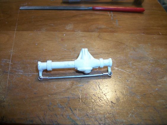
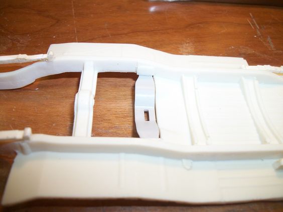
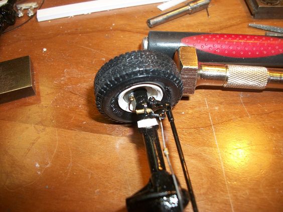
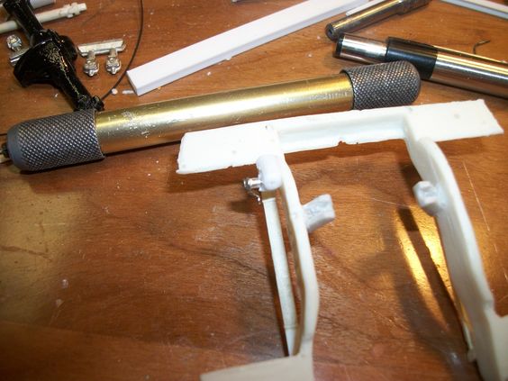
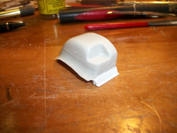
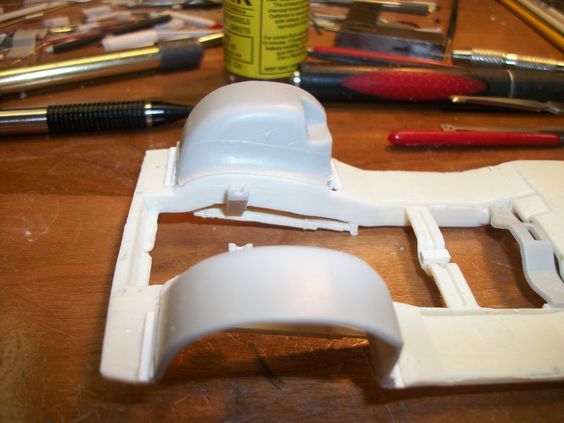
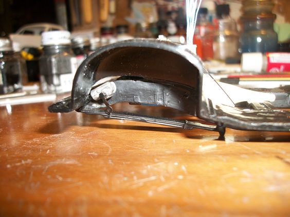
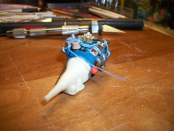
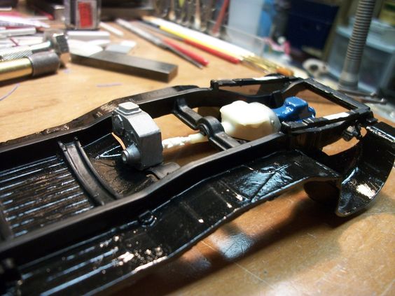
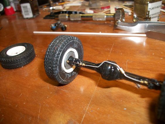
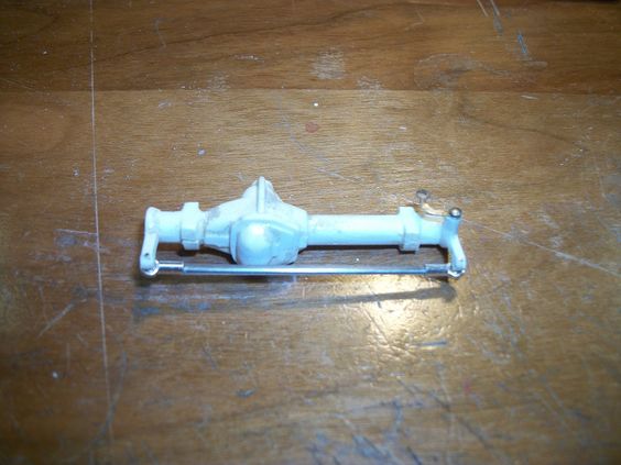
Same front axle, flipped over looking at the bottom! I got to paint this thing an getting it ready BUT I may as well get as much detail on it as I can before it gets painted!
More to follow right after these short messages! ENJOY!
 
So as I mentioned, I didn't get "A lot" done, BUT what I did get done was pretty intense. I got the front axle ready for paint, and some more details, BUT I also got the tires on rims, and some detail done to them as well!
b84e87dc1c2e0332926ea03eaa4fbd0a.jpg

White spoke wheels, on the times as I pictured earlier..... Looks really good! I got to add chrome lug nut bolts yet and the front set of wheels needs to have some sort of lock-in, lock-out hub assemble done to the rim but other then that the set of 4 look really good! (I have to also make a spare), BUT with a white steel wheel on it! -Which is coming too! I got a spare steel wheel to use, I just got to do a little detail work to the wheel and then paint it white!
b5a6969efef4e527dfcab734379f9d55.jpg

A little different angle and a bit closer.....
c6d66e9669d4b9bafa1cb85a7bdc6b44.jpg

NOW comes the fun! Flipped over tires! Top 2 side-by-side are the front tires, and the lower 2 side-by-side are the backs! The top 2, have disk brakes, (rotors) as you can see, with calipers, the rotors, and calipers I MADE! The caliper has a hole drilled in it to except the brake line and fitting! BOTH sides drilled to have the caliper behind the axle center, as the real one would have!
Then you can see the rear tires with DRUM brakes, Again, the DRUMS I MADE! I have yet to drill them for the brake line and fittings!
a77797035ac0c75b024350c1b0b8a5c3.jpg

Being "pre-made" these ALL will be "directional" to the truck! I want to get the wheels and tires on the axles this time BEFORE the axles are mounted ot the suspension, to adjust the height of the truck accordingly to what my Dads would have been! Building this way, will allow me to do that, AND add as much detail as I can just like I did my model of the truck I was building way back when.....
Next part to be handled is the rear axle! A bit of work needs done before I can get to where I am on the front!
Thats it for now! More to come when I'm able, ENJOY!
 
A few more "updates" on this build..... Not much, but something, something meaning a bit of "small" details ready to go! I too kit upon myself, to make my own "power steering" on this model just I did on my truck in this build, as the kit, neither of them, came factory or stock with such, and me, being me, I LOVE details, so I just HAD to add it! With that being said, a part that came from the stock pil 'O parts I got, I salvaged the lower power steering, that leads to the drag link.
59dcfbe65cfad97fba5914b8e6c831d8.jpg

Granted, as you can see the white is the power steering "housing", that I had to remove the steering shaft from one end, and make it go on the other (NOT added here), with that, I needed to make the drag link, which is that metal "dog bone" detail seem here as well as "pin" it to the steering box, and have some sort of "spacer" as well, which is out of a necklace kit I bought for numerous detailing uses.... Fittings, spacers, you name it.
740b7bb0a1036d49a1479557787230f5.jpg

Same thing different view. To show "depth" of the detail in itself. It will be mounted OUTSIDE the drivers side frame rail! As you'll see. Remember this truck is a bit different from the common "Power Wagon" we all know and love! I got a bit done/added to on the frame as well. I went and am still working on the rear suspension to get it "level" as it was all broken up.... NOW however its being done with heat! As they're solidly, mounted in place on the frame for the rear axle! BUT, I got to thinking AFTER mounting the rear leaf springs, what about the transfer case!? Hows that going to "sit" on a "low" 4x4 truck? As the actual model itself, seems to have been "lifted" and I brought it back down to "family 4x4 truck" standards.... I did NOT want the transfer case to sit so low that it was barely off the ground, BUT to sit in such a way, it wasn't to far up in the frame to cause alignment problems to the cab with the interior tub. SO, I got to looking a bit and needed to make some more modifications, to the frame.
6fbac9e3e0d51995d4fe9665f0e93103.jpg

The dark gray part is the transfer case mount. The whole square inside the frame rails, and the webbing" between the cross members had to be removed. As I needed the thickness of the frame to get the new transfer case mount in it! And "high" enough to look right. I even went as far to relocate the transfer case "cross member" mount, to the HIGHEST location of the locating blocks on the insides of the frame rails. To look as an "angle" mount from the cross member part of it, (if any of this makes sense)
42304db7657ee6d3d5e0921496aa32fc.jpg

Then while messing, I went to "sturdy" up the rear leaf springs. These things were/are brittle as they're old, and I MEAN OLD, and were from a Glue bomb I mentioned I got for mere parts.
76313a3eaac0d4f5ac0c5967cfc6d04d.jpg

A LOT of little things, to allow me to move on to the bigger things.....
MORE to come just after these brief messages!
 
Now, a LOT of really little work all on one sub-assembly of the truck. The front axle! Brake lines, hard line and hose and fittings, you name it. I made my own front disk brakes with added calipers from another glue bomb I had.... All to be put together on this truck to make it look the part. Just like my Power Wagon, earlier in the build, I had to make A LOT of the axle parts myself, as I do not think nor believe details as such are even made for us in this hobby BUT, I'm not complaining, I'm saying it as I enjoy seeing just hot far I can push myself, to make different details like this!
f084316aed60465a0e5da74c4195a290.jpg

Passenger side tire, rotor, brake, all the lines and ALL the fittings for that side, as well as brake line "hard line" to mount made and placed on rear differential casing.... The "hard" brake line in silver, has a mid-line "T" fitting to have the line front the master cylinder come down to it from a hard line ALSO to have a fitting to have a hose to meet this "T" fitting...... A LOT of "line-work", hard piped, and fittings to hose and such..... the "hose" you'll see from me, won't be "braided" its all as factory in this builds, as "rubber", right to the brass fittings that I make myself!
21490505264f731174f913d3e0009e9e.jpg

Just the other side....
7c41b485316ddbf1594ea8e31e41a329.jpg

Same side bit better view maybe..... You can see my rubber brake line hose from the hard pipe on the rear, to the caliper on the rotor!
In these views, you may be able to also see, the "mount brackets on either side from the ends of the hard pipe to the hose that goes to the calipers..... The hose is needed for the knuckle movement of the steering axle.
79e0f1d0379aabfc1a5f6839708ee935.jpg

A bit better side-to-side of the axle, showing a good view of the mid-line "T" that will connect to a hose that goes to the master cylinder.
3d2ec5206f418599f43811c0ae84ab5c.jpg

Over all view..... Not to bad for a couple hours work! Front axle is ready to be installed on the truck frame! BUT I have to get the rear one in the same shape first as then after that comes the shocks to the suspension, for the front. (Those shocks I didn't use on my truck), may come into use on this truck remember this one is stock height, my truck wasn't stock height! -We'll see! I'm pleased so far! More to come as I've made progress!
ENJOY!
 
So as I promised, MORE progress has been made..... To start out, as you all VERY WELL KNOW by now, I have a few of these trucks! (3).... BUT because of the difference from one to the other, I had to find ways to make things "happen"..... This is where it gets FUN!
I went and looked through the parts I had for the "stock" frame to the short step-side bed truck (I wasn't going to be using this frame on my "Dads" truck, I did however use the stock frame on my truck!) BUT that was due to Dads having a long 8 foot "straight" bed (Sweptline is what Dodge called them). But anyway, the frame on Dads truck I choose the resin version I had, as I need the styrene version for HEAVY frame modifications on the frame rails to handle a utility bed. Meaning, the factory frame that came with my Dads truck model was of the short step-side bed, and wasn't going to be used on this particular truck! WHICH, is what I'm getting too here.
That short frame, I needed the inner fender wells from it, to fit onto the resin frame (was resin cast without them) SO, I get out my handy razor saw, only to find that particular blade too wide to make the cuts needed to remove just the inner fender wells, without "hurting" the frame all too bad (I want to save it for a rainy day!) SO, off to look for a more suitable way to remove them, and went looking through my handy blade selection I have for thee ole Exacto knives I got.... Found a "keyhole" type blade, thin and pointy at one end with some serious teeth on it. Will do the trick! I get out my pin vice, drill a hole just big enough to whittle the keyhole blade, in through it to begin "sawing".....
Here is the frame, BEFORE I began all this:
ef838090b01ebb61e490a9da430775b6.jpg

195c60f2bf92e5415fd11c47f7992b55.jpg

Clean, nicely cast, it ought to donate well to the cause.....and it did!
eb521f5cbef2c3c125294702655e1143.jpg

Left the frame a little bit of a mess (I'll have to clean it up), BUT it donated the inner fender wells I need for Dad's truck......
8e083356db55a524424e2b3e4c50f853.jpg

BOTH inner fender wells, came off nicely, and I got one cleaned up right away to see what all might be involved, I'm glad I choose to do this the way I did, I kept the donor frame for something later, and gained the needed inner fender wells for under the hood of my Dads truck in this build!
More to come right after these short messages! ENJOY!
 
-So, while I was thinking on how I was gonna go about he added inner fender wells, I got to thinkin', I probably ought to get that steering box on the outside of the drivers side frame rail, as once the inner fender well is in place, getting to that or making the inner fender well fit, this be thee BEST time to get that in place!
4bbf62b4c2ba2c8cafb215c572023234.jpg

a6ce385d4822aa60f8c4595a646f86b1.jpg

4b5f86a7953ac97b2fd13cac03ad5de7.jpg

A picture to show a bit of "depth" of the actual added detail:
1ca49169d2587944036968e3b42a42e6.jpg

Then in these pictures I went ahead and did some fine "clean-up" of the edges around the wheel openings in the floor pan to take the inner fender wells without a problem....
3f8f7a094b5fc3311e306e59637e1ac2.jpg

The seen pencil line on the frame rail "side" is the location of the CENTER of the axle placement on the suspension, to center the wheel in the opening, and center of the fender itself on the body, and be even on both the front and the back, spacing. This WILL disappear when the frame and underside is painted, BUT will guide me, when I go to tape off the location as to where the axle will glue to the leaf spring, and allow me to glue it in place when the time comes. ALL the mounting locations will be taped off before the frame is painted!
4d9102814e988fe66bcafa6bca65a49b.jpg

EVERYTHING is looking good about now! SO, stay tuned! More to follow!
 
Then once I sat the frame aside, I began trying to "fit" the passenger side inner fender well in place on the frame. Only to find that the stock resin cast opening, was to large to add it as I removed the plastic one from its frame. I wasn't going to cut the floor pan of the plastic one, in order to fit it here, (be difficult to mud it in to look the part, SO, I went and added shim plastic to the inner fender wells, and a small section of angle plastic, to "glue" to the adjoining floor pan! They look a bit rough, had filed the first one (passenger side) right after its removal and before the drivers side was removed....
d3692dc6908456980114b4bd678817e9.jpg

One filed up nicely and one was removed, and then this picture was taken!
95f78371dbb194f972073866370738bd.jpg

7e306e23094827b43a4162b17b3429a3.jpg

Contoured GREAT, and corners "notched" to fit around the frame rails!
a39fe0d4c98205a19bd26d82eb232e4a.jpg

Un-cleaned edges on the angle plastic mount..... BUT it is notched here too!
Then came the FUN..... The drivers side! REMEMBER I added that steering box? WELL because of my "detail adding ways" I had a fun time contouring this one, as with my truck in this build, I added power steering lines from the pump on the engine, to the steering box, mounted to the frame! And whats stopping me from doing that same thing to this model? Absolutely NOTHING! SO, having said that, I had to contour the inner fender well on the drivers side, to accommodate both the power steering box, on the frame, AND the power steering lines from the engine, as well as the steering shaft from the steering wheel!!! I added that also to my truck!
5b515e3460106d57717ebe6192f6626d.jpg

It got that treatment as well as the added shims, and angle mounts on both ends!
eb576ffa998a12771f75b7ca6499e4c8.jpg

I have to say "contouring" wasn't too bad to get the inner fender well to sit in the same contour as the frame, the contour trouble area was where that steering box was, BUT, I managed to get it to fit and look good all at the same time. MOST of this detail for mounting purposes, will disappear when the truck goes together as the rear will be covered by the firewall, as well as the front with the radiator core support, and all the detail on it, BUT, is needed "extras" to mount solidly to the frame!
3e38b4ec1791415f29b003edda8b8d63.jpg

Front of the driver side fender well...... Cleanly done, and ready to be put in place!
More to follow!
 
OK now that BOTH inner fender wells were removed from the donor frame, and cleaned, and then sat up for installing, I got right to it.....
731f497199ec0b9a424f87a422dbb40a.jpg

Looking at it from the passenger side of the truck, you can see the opening in the fender well to allow me to add a steering shaft from the steering wheel, as well as all the pipe work from the power steering pump on the motor.
2937771015b9245df1daf34f6a051fb7.jpg

Looking from the drivers side.....Granted, BOTH these pictures show the "open" corners.... I have to go back and "fill" those in. ONLY the opening for the steering will be open when all said and done!
Coming up next, is something NEVER done.... These 2 trucks had never seen each other unless in passing, I took the 2 models to see if the height from one to the other was good for both trucks "stance"!!!!!
Stay tuned!
 
As I mentioned in my last post, I HAD to see what the stance was between the 2 trucks.....
5c3323c9467bd8f749794a3ba14b155e.jpg

My Power Wagon on the left, Dad's Adventurer on the right!
745000e0bdbfad18a296edb9456e52b9.jpg

Under a bit more light......
78db0868eca57cf1194fb13e12e9b1df.jpg

I say, the stance is PERFECT, my truck was built to sit high, as it was, the real ones were about as you see these 2 models, Dads truck on the right, needs a bit of work to get it where my Power Wagon is, BUT I think this is GREAT!!!!! Mine was was built purposely to sit high (I wanted to go muddin' in it) Dad's was a "family 4x4 truck" and sit at a high "stock" height as he added slightly bigger tires and rims to his.....
I'm VERY pleased with this work so far, on BOTH trucks! Got a ways to go on my Dad's, BUT it will happen.... I got to sit and detail up the rear axle for his and then figure out its suspension as well as shocks for both..... Ought to be a fun task! SEEING these last few pictures of both trucks front-to-front like that...... WOW!
As always, more to follow as things are done!
ENJOY!
 
Well after a bit of time and a good weekend to keep me out doors a bit, I actually got a bit done to the truck in the evening!
So, without going on an on, hows about a look see to what I did!?
c27afad463c20f001caa7cf61a4024f8.jpg

Seen here, all "clear coated" shiny...
Frame got painted, and clear coated! Sadly, however the paint on this frame is a bit "odd" looking. I think due to the frame being resin for one, and 2, the paint when I went an cleaned up the air brush, seemed a bit "think" I guess, as it was left over from a pre-mix I done a while ago.... Was flat paint, and With my dad he had "undercoated" every vehicle he owned so..... The frame got a slightly different treatment, I'm not sure what that was to consist of, BUT was flat black as told to me by my uncle!
SO, with knowing that, I clear coated the flat black frame, and then allowed that to dry and went back and dry brushed dullcote onto the just the frame rails and cross members.
4beaf95419dcabef8df8af29527785a5.jpg

a030178bbe2917a2a147bbba158e0893.jpg

Dullcote added to the frame and cross members!
More to follow these short messages!
 
Then while at that painting, on the frame, I got the steering box, painted and detail painted, all in the while AFTER the spray painting was done, as the steering box would have been a cast iron steel color. Which, was unpainted like the color of a unpainted transmission (they're normally a matching color of bare cast iron)
c016038a1a77a39c4a3a9d4815d9064e.jpg

Then a bit different view showing detail painting I did:
6ea4a084bf1a6207370140f705bfaff8.jpg

6da4e2f2473717bb19511ae3ca663590.jpg

These 2 pictures show the gloss black bell crank that needs a ball joint, rod to go from the open hole, to the jointing, steering bell crank, on the axle spindle....
I have yet to make this part.... This won't be made to fit till the axle is ready to go into place on the front suspension!
More to follow after these short messages....
Enjoy!
 
While that was all setting and curing drying paint, or glue.... I got the transfer case loose from the donor frame, to refurbish to usable standards. Just like the transmission will be and the steering box, the transfer case would have also been a cast iron color of steel.
e6d6948279b9e0ca9c6fae8f3b9007f8.jpg

Cast-on detail wasn't real bad, BUT it needed something more..... A good ole oil/grease pan was needed (factory detail part was merely "flat" and was a 2 part detail all together, With the added "pan" detail painted bare steel color, as it would have been, I made the part from 2 small sections of plastic sheet, one thicker then the other as the "lip" would not have been real thick anyway, BUT the sump in the pan, would have been..... I have yet to add one last detail to this part, as it needs a drain cock for transfer case fluid changes.....
15bc3562f7df28a8a6b01bc8d2b2a3ee.jpg

Short message, more to follow this one!
 
SO, as I had firstly spoke to the uncle, this truck of my Dads, got some decor, added to it, firstly (I should have known) was the stock valve covers, removed, and replaced with chrome ones that were OEM chromes covers that were Mopar made.....
bee676f78cbd32a7f3a5679887c2ea7b.jpg

Then if you look, I added the distributor, and the exhaust manifolds. This truck, unlike mine kept single side exit exhaust. Meaning, I will have to make a cross-over pipe to go from the passenger side manifold, the the drivers side, in a "Y" pipe.....
Not sure what oil filter Dad may have used over the years, BUT I added mine to his truck as tho it was a OEM "Mopar" replacement part, in white. IF I can find a "Mopar" oil filter decal, before the engine is ready to go into place, I may add it to the part.... If not, "white" is good enough as the decal depending on location, wouldn't be easily seen anyway!
7ab81c0417dfbc68ad0d04999f92fa96.jpg

The other side of the engine, missing the exhaust manifold, it was drying when this picture was taken. I did however get the starter in place, and if you look closely, you can see the carburetor linkage and return spring in place.
The one thing this truck have had, was the California Omissions items, I KNOW without asking anyone that my Dad had removed these, (wasn't required to be inspected in the state of Pennsylvania.) SO, those parts will be omitted from the build!
70ec347f1922acad1498a9c9b0d57571.jpg

A shot of the back of the engine. I have to add the PCV valve, and hose, as well as some other small things. I have to add the transmission fluid dip-stick not seen here, as well as paint the transmission, (I wait till last to paint the transmission as I use it as a "handle" to hold the engine while detailing it.)
5c81f81c0312018596e2297475056ec3.jpg

A NICE head on view of the engine. A Mopar 360 4 barrel..... I need to get the holes drilled for the plug wires, and add in wire looms.... Those are next to be completed! -I also need to make an oil dip-stick that will be added to the left side of the front, of the engine.
A short and sweet update to follow....
 
And for now..... Last but not least, I was working on the frame and got to looking, theres a nice location for the spare tire! I took the last tire I had,and got it ready for a spare on Dads truck that will be placed in the stock location....
The tire however, wasn't the best tire, the hole was trimmed (or so it looked) that the rims I needed to put into it would not fit, SO, that gave me the idea to take this 5th tire I had to make an actual detail part with it!
Dad himself, did not have a matching rim for the spare, BUT what he did do, was take an old Steel wheel, and have it painted, (NOT sure if it was paint, or if he had it powder coated like he did with the spoke'd rims) But it was in fact "white" so..... I took a spare one I had a as an extra, that matched no other steel wheels I had, painted it white and it got glued into a matching tire......
f455694cb44d09fb9fb4dfee78df9656.jpg

Rim glued in, center drilled out.....
4c2c3af88ae289d59c4757041eb91bc8.jpg

looks pretty good! My next treat to this, is drilling out ALL the lug nut holes! It would have any lug nuts on it, as a spare, right?
ENJOY for now! More to follow when progress is made!
 
SO..... it has been a few days, the rain stopped and the weather got nice, and ole John had some out door stuff to do and yet got more to continue out doors but I did get a little done!
I took the engine and got the plug wires, and boots in place....
24eb2f9c63524cb1d18ed58822bc55a9.jpg

I also got the valve covers on the engine too (I almost forgot that the last I posted), the engine had no valve covers or anything for details up top! The valve covers ALSO got wire looms mounted to them to hold the plug wires!
2a90507d884d2b1238e32a629a861df9.jpg

The wire looms are how I "directed" the wires to lay as they are too!
eba2e79a6533fd7f2b13c96438cafb71.jpg

Just the opposite side!
b51d781149c60172d9487e240295c583.jpg

Back of motor, showing the coil wire "loose".... BUT the coil in place! (The coil, is a in-shop made part! This model (just like my truck in this build) did not come box-stock with a "coil" detail.... The "silver wrap" (mount in real life) was made using scrap BMF!
041c7397741574db0212c87c659ccc9c.jpg

Coil wire in place!
Up next, is short and sweet (I did not get a lot done to the build so far this week), but one more post to follow, right after these short messages!
 
So a little update, not much mind you, but a little..... As you all should know by now, I'm remodeling my shop, and most of the work benches..... Which will make model building and all a bit easier once done! BUT, in the evenings when the noise has to cease, I work on Dads truck in this build, just to keep it going, and not stop on it completely.....
SO, what I have done was searched out a "junk" drive shaft, as Dads truck would have had whats known as a Divorced transfer case, meaning it had 3 drive shafts! One from the transmission, to the transfer case, and then one each, to the front axle and one to the rear axle. The transmission would NOT be bolted to the transfer case on this truck, as it was on mine! BUT, because, I didn't want to cut up a good one, I took the donor frames "front" drive shaft (not the best of quality of details), BUT had half ways decent "u-joints" to be salvaged from it to make the needed one to go from the transmission to the transfer case! REALLY short one I might add, there is no real "shaft" to it..... Mostly all "U-joint" detail!
6b157204f98f554a3c395c4842dd58df.jpg

857b6531f8858e546412856d8879e50c.jpg

52d79993663cfdd67805b938062b6c60.jpg

Notice, the engine? Its upside down! WELL I had to get the plug wires to the locations in the head in order to make this part happen, the loose plug wires would NOT have allowed me to flip it over like this to "fit" the first drive shaft to the frame! SO, that was a pre-step, I had to do in previous postings of the build, as it all goes together like a jig-saw puzzle!
Thats it for now, More to come on this build as I am able and have the shop in somewhat of a orderly fashion! (I got my work cut out for me!)
Enjoy, for now.....
 
Well guys, As you all know, I have been busy..... Before Fathers Day, as well as this past Thursday, a few know I was in the hospital for a day procedure that came out OK, I'm a bit sore, but to have a stent added to either leg is a bit of a task on the person having it done so. but anyway, I'm doing good and feeling "OK" just a little sore" but handling it pretty well.....
As you all know (or so I thought I've mentioned) I lost my Dad a little over a year ago, now (was a year in March) SO with that, and have had thoughts of him on my mind with the builds a few of you of/from me, this Father & Son build was directed towards this whole thing, and Fathers Day, all I wanted to do was relax, (because I had too) and work on my Dads model in this build (because I could), in honors to him, and thats just what I did!
This is one of those postings, to show a little of a lot of little parts, small details that will lead to much bigger sub-assemblies in the near future!
So with that, I got to thinking how the rear axle needed to go together, and got to looking at where I left off on it. THEN before getting into that looked over the frame to see where I was on that (kind of "reflecting" past work), and where to "pick up" again, so-to-speak....
So, I took the frame, and thought,A LOT had to go onto my trucks frame in this build BEFORE the axle could be placed onto it, (I WAS NOT going to attempt working around a mounted rear axle!)
970d8b836b518013938f889d1203c4df.jpg

6176834fe6f270dad5452ebb0f0e0c14.jpg

Very "end" of the rear brake line. This is the "hard" line that goes to the mount seen mid-frame, to a fitting, that will run forward to the brake master cylinder lower manifold.... The hard pipe itself, has a fitting on it, that carries it through the little angle iron bracket on the frame cross members! This line was made formed and placed for the picture. I had been removed, painted and let dry before gluing in place! The fitting is now brass colored, and the line is steel colored, as these had steel brake lines!
e440dab56e85d5fc9d54e35cf5420c04.jpg

Just like my model trucks frame in this build, the brake line will follow the inside of the frame rails, in the corner of the frame, where it meets the floor boards, all the way to the front. My trucks frame was built this very same way! Only difference is Dads truck was 2 scale feet longer then mine! (He had a full size bed "Sweptline" so.... mine was Step-Side short box.
452f84300353eea2414b8b9912611179.jpg

dcbff75ea3a8eb204ba49e00ffcbc5a2.jpg

As you can see, I went through drilled need mounting holes, and got the copper line ran to be in place, got it all fitted, and then, removed it all to paint:
830589c42bc352be9e853193901e7e88.jpg

Which means, this step to getting the rear axle in place is complete! NOW, I got to get the engine in place, with all the exhaust pipes in place in order to get the axle onto the rear suspension! I got a ways to go! (Thats what I get for taking the time to remodel my shop!) BUT the things I have done in it to date, has been much easier, much more user friendly, and way more comfortable to do with it set up as I have it! -SO, that alone makes the time WELL worth the effort involved! -HOPEFULLY LESS "make shift" tables in the near future (Unless they're in MY WIFE'S side of the shop, then, I don't care!) LOL
Engine work coming up next! ENJOY....
 
Well as I mentioned, Engine work was up next......
I had to add a oil dipstick to the 360 in this truck, which was a fun added part (I make them, myself, paint the "tube" install, into/through a left over wire loom and done......
3592806a5abf17ebc56c2633595e017a.jpg

The "chrome" loop is just in front of the valve cover, difficult to see, BUT you can see the shadow of the wire itself, on the engine block, just behind the fuel line! Very fine black line. I will attempt to get a better picture of this next time I snap pictures its such a small detail part!
Then, what took the most "patients" was the engines pullet and belt set up..... What a task! I needed to incorporate the following:
Water Pump
Alternator
Power Steering
Air Conditioning
Crank
and a single tension pulley
What FUN that was! I took a few "glue Bomb parts, broke factory belts, and removed them, chucked the pulley in the Unimat and left 'er rip.... Spinning the pulleys back "round" again, to wrap Evergreen Styrene around them (as belts) for strength, and then flattened the outer most pulley glue bomb, to use to over lay it onto the rear ones, and make it all fit and look the part.....
I *THINK* I managed to get 'er done!
722125a4810d1cbbbb7673299353fb59.jpg

44ba29eaeac5fde37da6b87fe1649a04.jpg

Blue pulley to be the crank pullet, black one to be the water pump pulley, the very highest mounted one A/C Compressor pulley, silver to the left of the AC pulley is for the Alternator, and off to the right is power steering MID-mounted silver pulley a tensioner pulley.
I'm NOT 100% sure how this was to all be under the hood of my Dads truck, BUT because his was "stock" and NOT trusting on-line sources as being 100% honest to the stock location, I set it up as best I knew how and look right..... Got to remember this truck is/was after all a 1979 model Dodge! A LOT can be changed over time so..... SO, I tend to go with what little I know added to the know-how on my own truck was, and thinking how it reflect on a slightly different truck a year newer.....
I do think however, I pulled it off! -It really isn't a "detail" thats going to be fully 100% seen when all said and done ANYWAY, so only needs to "look" the part 100% top end! -Which, that I know is 110% accurate!
Tedious little details done, MORE to come as I'm able! Enjoy!
 
So, on Fathers day, and a little bit yesterday, and more will come after tonight..... I did get some done, but could not "handle" for pictures and so, had to wait till I could.....
Our very own "Stray" had posted pictures of his "spare" wheel on a build, and his persistence, on showing me what he had done, I simply did it on this build! I wasn't originally going to "open" the "slots" in the steel rim, BUT....... He persuaded me to do and do it just for looks sake! And with that here is how mine turned out! (THANKS for the inspiration Stray!)
I took this:
4c2c3af88ae289d59c4757041eb91bc8.jpg

To this:
159f1bd1cc4ea84a3a32ff5c9e8c57a9.jpg

With flash ---^
3c6bc2b7feaf7ae985a17d5d942fb5de.jpg

Without flash ---^
I think it came out GREAT! I like how it looks even tho when all said and done, and in-place on the truck it won't be easily seen! BUT, theres more..... Me, being well, ME, I took it a STEP further!
The truck, has to have a spare tire mount, in the "stock" location under the rear portion of the bed..... SO, I took the frame, and began measuring to make one......
2e4d3eafcef2b28b16ca0c057e125545.jpg

Right now, it doesn't appear to be much, BUT ohhh yeas it is! This "pole" is mounted to a resin frame, NOT glued, its machine screwed to the frame! This will hold it in definitely, BUT I plan to also "glue" it to keep it from rotating over time, WHY? WELL thats why I say its something "more"..... The Spare tire WILL BE REMOVABLE! Once all is done and the mount detail is all added to the pole itself, I plan to go back to where it screw mounts and totally fil in the head of the screw in the top side of the frame thats fitted by means of countersinking the screw and all and will be covered and buried in the frame itself, NEVER to be seen again!
I have yet to paint this as I have some angle plates to add to it to date, so is left bare machined white styrene.
fd796c62802d9149a4687c8c25e16cb2.jpg

Tire "in-place". just setting there for now! I have to make the cross bar that will have a screw that will thread down into the mount pole that will "pin" the rim with tire to the under side of the bed, AND look as tho it can be removed with a 1/25th scale hand! NOT a screw driver! I however do have a little detail to add to this and then after that it all will get painted. Exception to painting will be the underside of the cross bar that will hold the tire by means of pressure to the rim, I do NOT want the cross bar to have black paint get onto the white rim! SO, only 3 sides of that cross bar will be painted!
More to follow, stay tuned!
 
So while I was working on the engine, and working on the spare tire, I also got to thinking WELL I've got the frame near ready for the rear axle, so why not assemble and detail it as for when I am done with the frame, I'll have the rear ready to go right onto the suspension!
SO, I did.....
2b230a740f349a87ca10d66be98aa708.jpg

Now, as you all reading should know by now, I had been taking parts from a Donor frame, to make all this happen, this rear axle came from that donor frame! Thing is, even in good shape, it was still too narrow to fit right and look right, SO, I had to widen it just a bit 3/32ns per side to get the width right.... BUT the issue with that came along as I was not using the stock rims or wheel backs! Meaning, I had to make a lot of my own parts to have this all come together. The wheels in the tires and the wheel backs used left NO rear brake drums! I had to turn my own brake drums, to fit the application. Which you'll see better views of in just a bit. BUT adding all that, plus having the narrow axle issue, I had to fit the axle casing with a turned "addition" to get the width right so it went from 3/32nds inch to something to the tune of 5/64th inch to get it close.... SO, I turned one longer piece about 2 and 1/2 the needed length that way I had the same diameter addition for both sides! OR some for error.....
Once I had all that assembled and ready to go, the detail adding was next! I took the rear, and added "L" angle brackets to hold the hard brake line plumbed on the rear axle, to these brackets on either side, drilled and then fitted with the pipe itself. Once glue was dry, I took and then fitted the ends of each with fittings, and ran into the rear of the brake drum housing. And then let alone to dry, for an hour or so, and once ready, slid the fittings to their proper locations in the line CA glued them, and let that to dry.... Once dry ALL got painted in-place. Brackets painted gloss black to match that one the rear axle. The lines painted steel, as per factory Mopar. And fittings painted brass, as per materials they're made from, and then from the brackets to the brake drum housing "rubber" for hoses......
6a95c19d2effc2c789553042ebf068d2.jpg

That large "brass" fitting seen next to the rear axle "pumpkin" is the fitting that will have a hose running from it, to the little cross member bracket fitting on the frame that will have a hose going from one location to the other. You can reflect this detail on my truck in this build, both were the same but slightly different. NOT by a lot tho..... I think mine was on the other side of the pumpkin, but the frame bracket was in the same location.....
3da0b51da418451f40cd48c7faee301c.jpg

Other side, same thing.....
Over-all it looks really good! Detail is spot on to a real truck of the same type and everything is just...................... pleasing to date! I'm happy thus far with everything......
Then as you all know, I made my own belt system set up for this truck, last you seem there was no power steering pump on the belt cluster, that has been remedied.....
ecac217ca2157c6d3215aeb58393fc24.jpg

I got to paint the "cap" to it flat black, and this whole detail assembly will be ready to go onto the engine!
One step closer to getting the engine in the bay..... THEN I'll be able to begin running exhaust pipe!
Thats it for now, more to come when progress happens! Enjoy!
 
Back
Top