• Welcome to For Trucks Only !

    We are a community of American Brand Pickup Truck and SUV owners. Join now! Its Free!

'65 Dodge A100 Monster Truck "Doomz Day" Model build

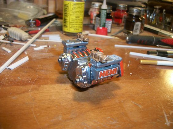
Well its been a bit, a bit of trial & error (I have to admit to it, I had some issues with getting this right!) BUT thats why I keep "trying"..... WELL, to give everyone a heads up, keep in-mind, I want this thing to be the BIGGEST, BADDEST, engine ANY of you can EVER imagine! To the point of, when you see it, it jumps out and bites you............. Thats the goal here (I mean, really its name after all is "Doomz Day", right!?) -NOT because of the meaning of the term "Dooms Day" but after the name of the engine that powers it.. the "Dooms Day Machine" Chrysler called it! BUT I'm playing off that, with the name and a little twist with the spelling, but you all get it by now. And, those who know me knows how I roll that way!
So anyway, to start, I originally wanted to use the 14-71 Superchargers that I molded and have made already.... Sadly, I wasn't pleased with their looks. They'd be OK on other builds, but not this one..... I just wasn't "feeling" them in the sense they'd be used here.....
SO, with that, I sat out to build something...................different? Yeah, they sure are "different". Kit-bashed, yes, from existing parts, made to be bigger then originally made by the factory. Started with parts from the S'Cool Bus kit, that I saved....
32c752620358cb12f7434d7ebab97a3a.jpg

Those Superchargers are monster-ous, BUT they are after-all 1/24th scale, NOT 1/25th so I made them fit the suit, and slightly under-sized them, BUT still kept them "BIG" for looks.... IF that makes any sense!
3f3bdf5830c2567494162889664c2e2e.jpg

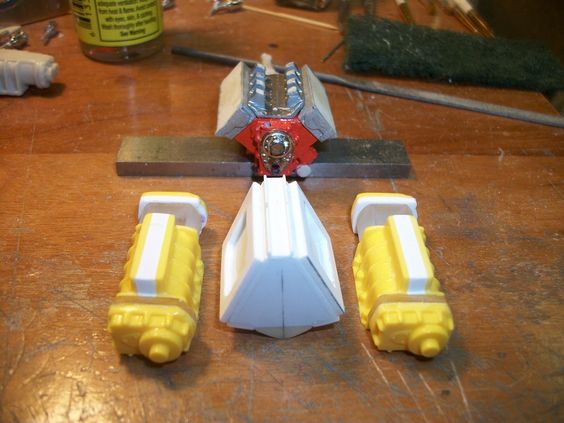
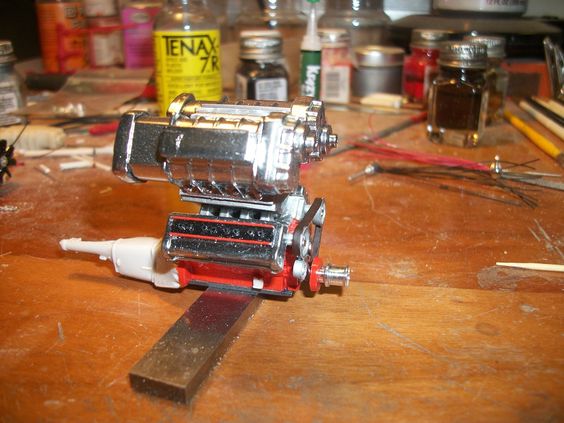
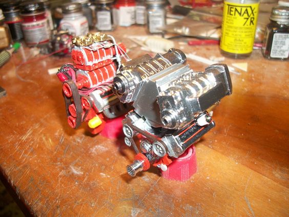
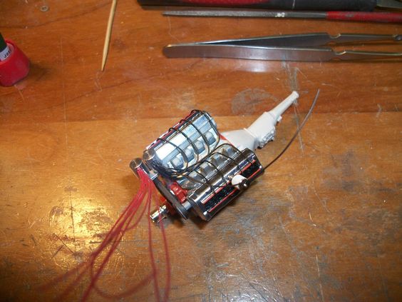
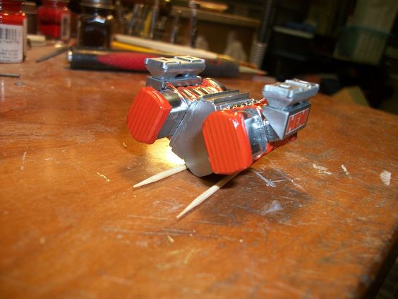
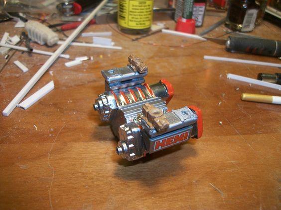
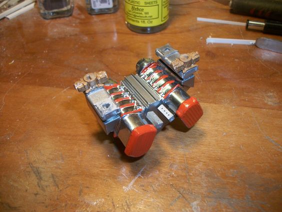
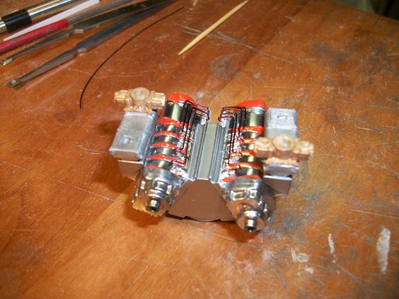
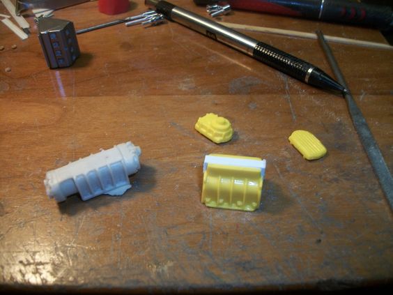
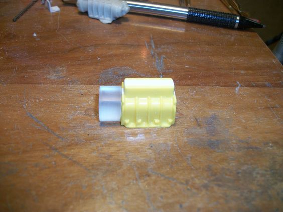
Now as you see here, I have the newest parts set out, with the first BIGGER idea I had, with the 14-71 resin part setting with whats to come! To start, I took the factory S'Cool Bus blower "body" and split it down the center.... This was going to slightly "shrink" it. Narrowing it, makes it fit the Plenum a bit better, and gave it a slightly longer looks thats not so wide. I re-built it adding in 1/8th inch thick rod, to the center, so I didn't make it too narrow but took out about 1/16th of an inch in width by doing this! SOLID bar too, makes it easy to "shape" it to the form, of the blower body itself! And giving a good base to glue too!
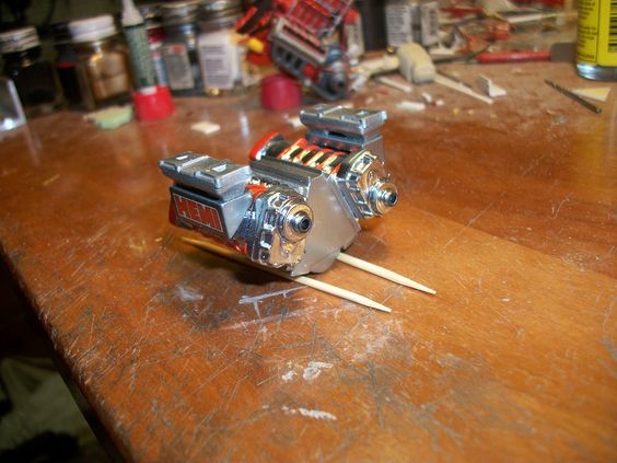
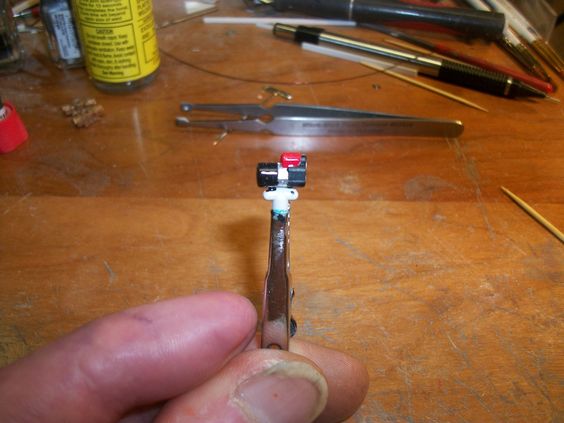
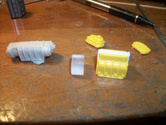
Then, you see the front and rear blower body plates, those have things done to them as well! Between the yellow blower body, and the rein 14071 I molded you see a clear piece, that I machined! This is a body extension that a larger then 10-71 would have! This will be added to the back of the blower body!
f60787e5bffa9b28a3223ab154af57a0.jpg

fd80e807301fffbf5b087f3253f0bd67.jpg

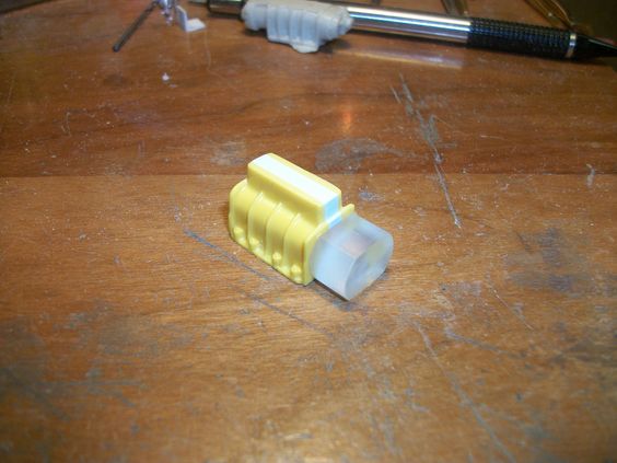
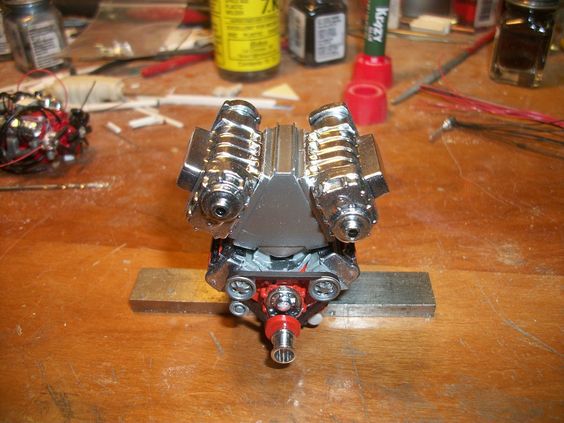
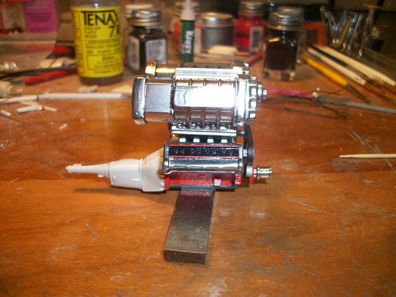
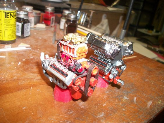
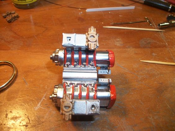
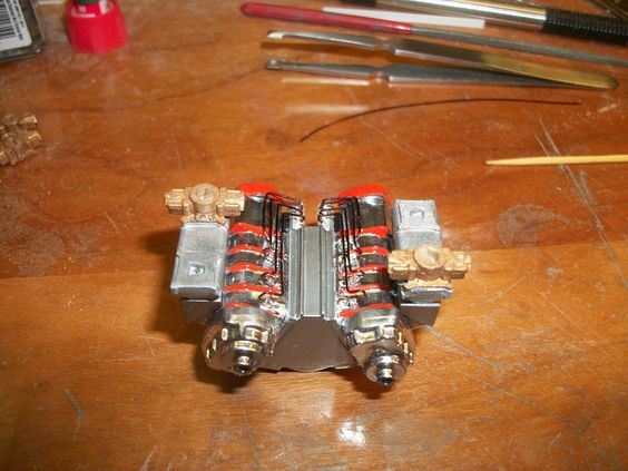
That clear part, mounted to the back of the blower body..... This clear part? BOY, I tell you, that thing was difficult to make and get it right! See, there is no "true way of knowing what looks right, what is too big, or too small! Because its "looks" NOT dimensions! Plus, in making that part, you first have to turn the part down to be round rod..... THEN when you think you have it, right, you then have to put it into the milling machine, to mill to flat spots on it, top and bottom! BUT, if the round turning isn't right, when you mill either of the flat spots, you can't go back and turn the round part down any further as the lathe won't grab the part right to make the turnings true! SO, one small mistake? You get to start all over again! Thank God, these parts are just little, It took 2 tries before I got the 3rd one (seen here) right!
64c729a7ad97f704a21d4ffcb5a9f64e.jpg

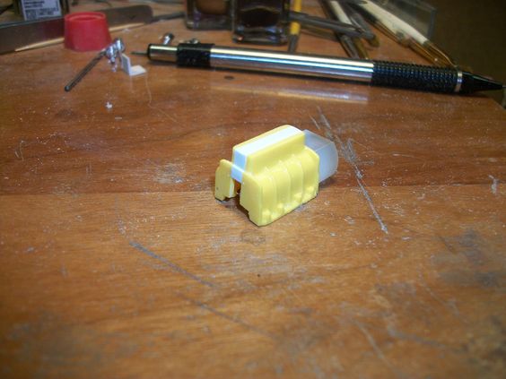
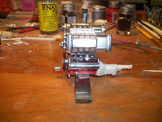
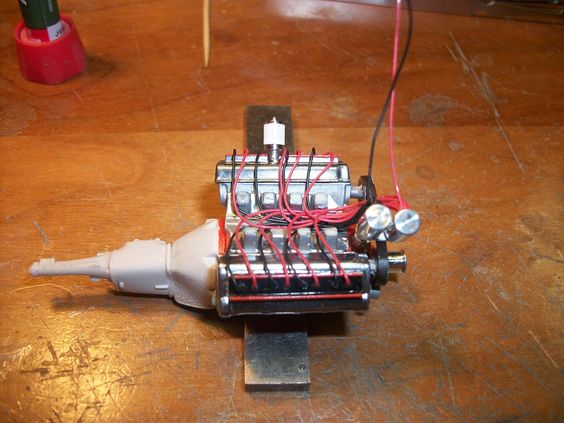
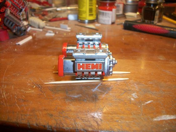
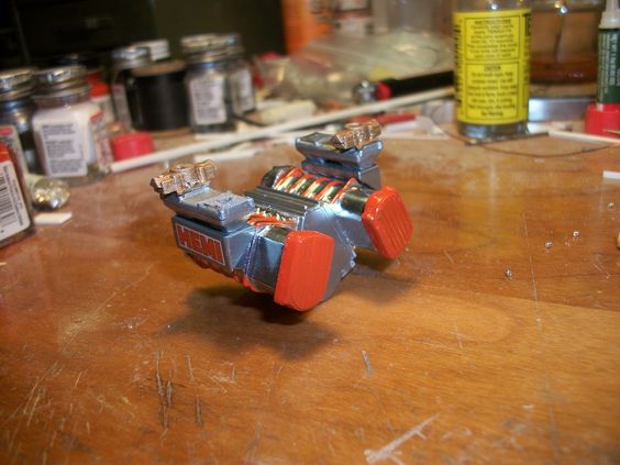
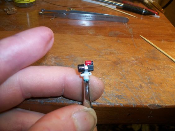
This shows the front of the blower body!
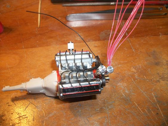
Now sadly, I didn't get pictures of the work done to the front and rear plates for the blower, BUT as your about to see, I did some work to both those parts as well!
3c1a25a731d45123a6dda6f3f391e181.jpg

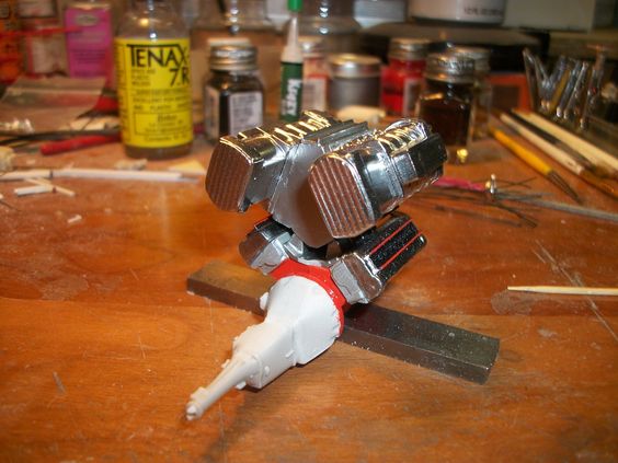
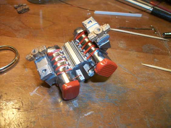
The front plate that has the blower drive pulley extrusion, got a thicker plate as the real 16-71 would have.... As well the rear plate, also got a thicker plate base too, these "extensions would be for bolting reasons, and flanges for such as well as size all in one!
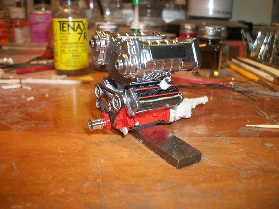
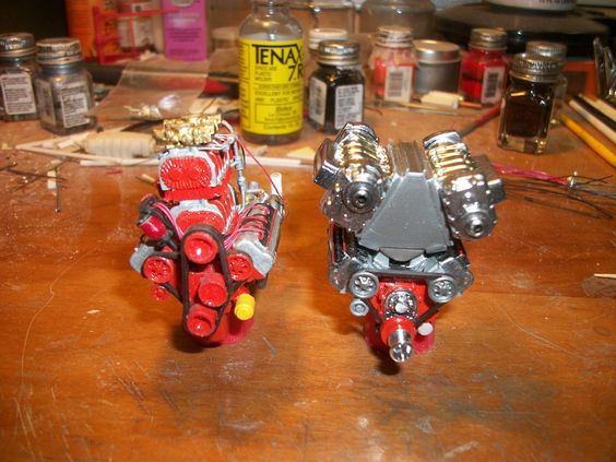
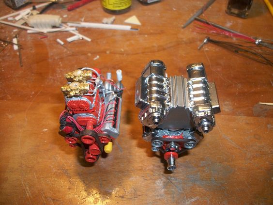
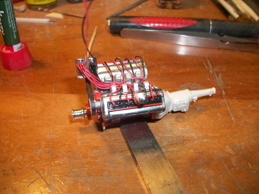
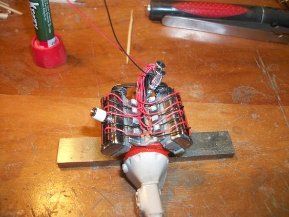
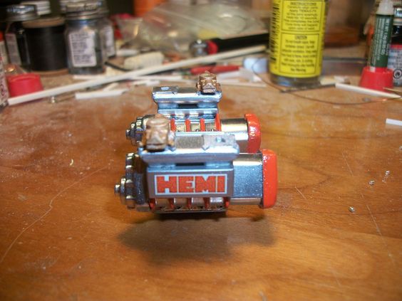
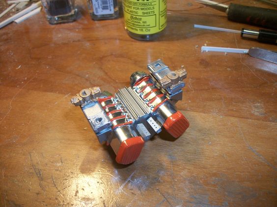
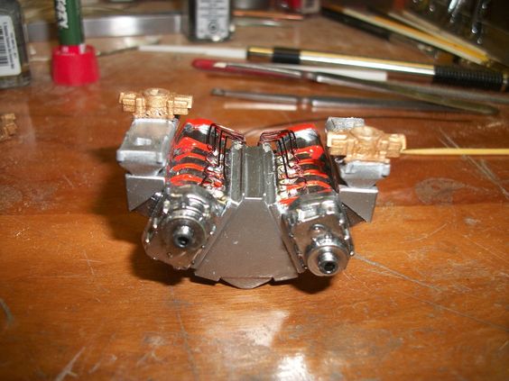
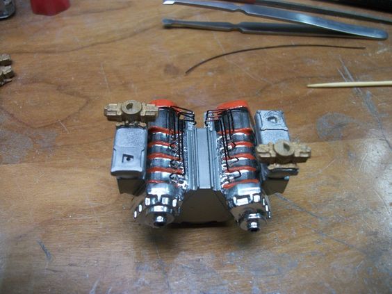
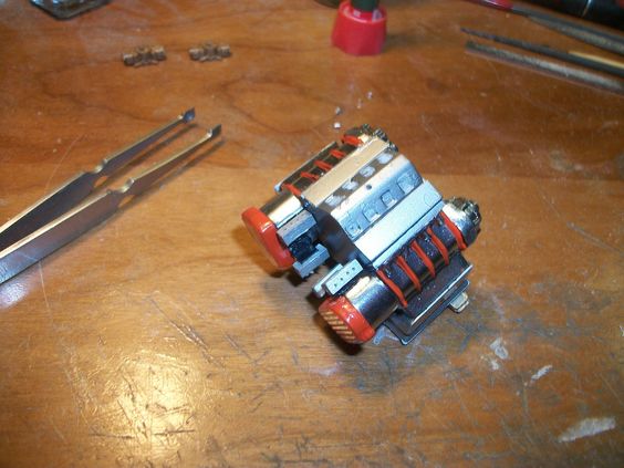
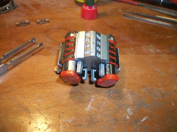
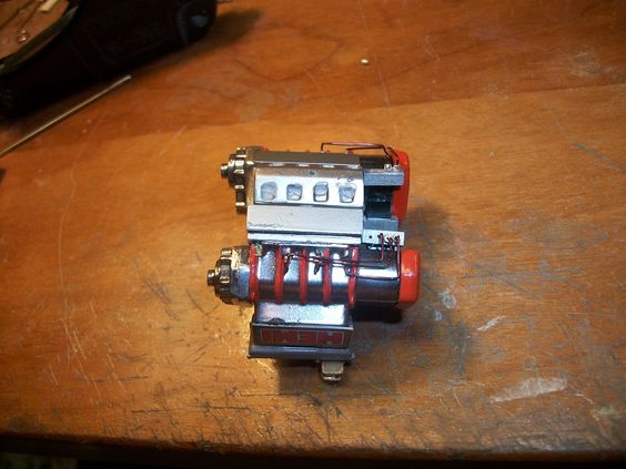
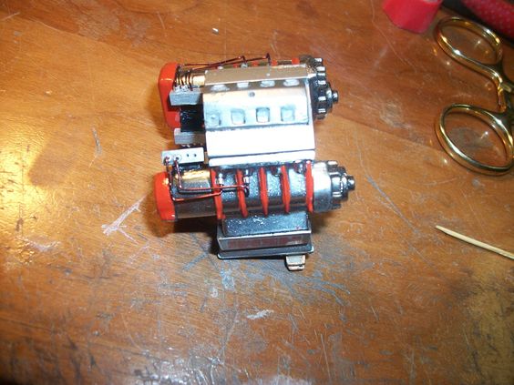
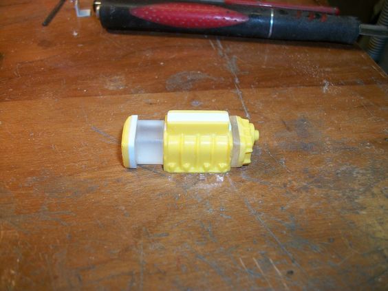
Now to take the resin 1`4-71 that I mold, and sit it right beside the NEWEST creation my 16-71 Supercharger....
84145bf0ec500f68aa694e126973b442.jpg

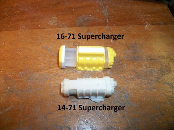
A tad difference in size, yes? I LIKE it! The new one looks GREAT! After a couple of tries, I find, one day, to let it sit and think about it, makes all the difference!
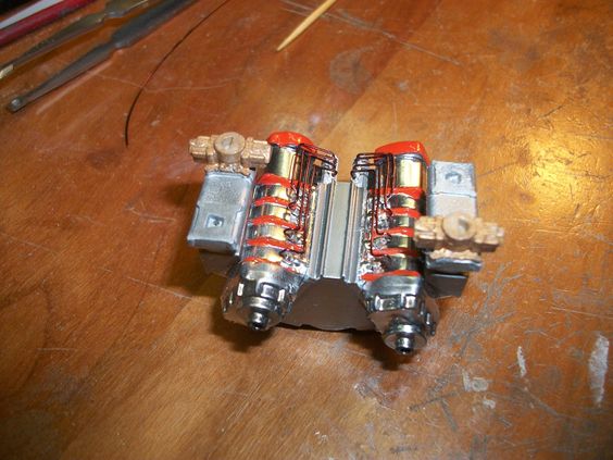
Now so that all are aware of it, I had to make these TWICE! As I'm using Double inverted-"V" Superchargers on this build!
Stay tuned, more to follow! Comments are always welcome, ENJOY!
 
So As I mentioned, I had to make 2 of these Superchargers, which I did.... Got it all "right" on the 3rd try! And then got to seeing how they fit that Tunnel-Ram Intake Plenum. WELL the "Foot" print of the supercharger was just enough, that I HAD To set out and re-make then Plenum too! GO FIGURE! BUT, the hard part was done on it! All I had to do was lengthen the height of it, and cut the point in the middle "in" a little, to get the new superchargers to fit the old sized Plenum, ALTHO, it made me have to create a NEW Plenum! Thats alright. The old original, I plan to mold and off with the intake "base" Tunnel-Ram ports! (To offer something other then) for that intake!
07a7c16fea02346baa2bb5cb0cafa45a.jpg

Two 16-71 Superchargers, and a new Tunnel-Ram Intake Plenum, siting & waiting....
Once assembled, the Intake set up alone is BIGGER then the engine is!!!! I'm OK with that! As you'll see in a minute!
 
SO once all had sat a bit, a few hours, I took and got primer on the Plenum, to be painted with Alclad "Dark Aluminum" to match the Tunnel-Ram Intake base.... -I then took and painted the Superchargers with glass black, to begin the start of chroming them also with Alclad Chrome paint through the air brush!
I let it all set as the painting step took a couple days to do.... BUT once it was all ready to go and be handled for assembly, I just could not hold back! together it went..... Then I realized, I got absolutely NO pics of it going together..... Ohh well, heres what it looks like TOGETHER!
571f16df7a1792d41db6adfdd6cc9698.jpg

b17adbd2c7324bad8f3da8a7522494f9.jpg

e4c848ff3224394009c18a5583794c69.jpg

6685f722aeaa27f0667b98ce89d926f8.jpg

90de9de874f86ada35ec940fd6bce3d6.jpg

be09a1d1abb8bd38013a01b2eb0e6df2.jpg

W-O-W......
I'm AMAZED at just the sheer size of this thing! The engine is BIG, YES, but with that induction set-up Holy Mother of God! And to add to this? I'm no where NEAR done either! I got the plenum with the superchargers on the engine, to stay, as well as the valve covers, as well as the first phase of belts! In the back-ground of the pic, you can see the awaiting Distributor/Magneto's, with wires! The superchargers are mounted in such a way on the plenum that ALL the custom turned Billet Aluminum pulleys will line right up for the belt! And thats gonna be a FUN ONE! I'll enjoy it tho! This whole INSANE build, I'm enjoying so.... Stay tuned, more to follow!
 
Now to get ya all worked up....... BOTH the "Old" 426 DOHC Hemi, beside the "NEW" and improved, 528 DOHC Hemi!
6446f5e4a9e01ae4beffbc2f28b100cc.jpg

6d5e416bc8f315b0fb1ee8017172c456.jpg

4411c402fe0a30508841bbaa25a5c8ae.jpg

b069ea2d6a8701b6111329a0c604ecf4.jpg

Nice! The 2 of them side-by-side are almost "equals" in side! I did NOT set out for this purposely but is an added bonus I have to say! The new one will be made to fit into the trucks frame just as the first one was, and that way, all will fit right from there on out for the build! I am keeping the exhaust pipe work the same as I had planned. Also the Twin-Turbo's will be made exactly the same, as the radiator and intercooler are not in-place yet so, there is a little wiggle room fitting all this and making it right!
The one thing I AM going to do, it fit a plate to the center line of the Superchargers to have a "level" setting set of carburetors on EACH Supercharger! SO, they will be "level" not mounted on their side type thing... keeping that "Long-Ram, Tunnel-Ram" looking effect! LOL
BUT, now in order to keep going, I have some details I HAVE to add here, as if I go any further on the build without detailing, I'm gonna pay for the mistake! LOL
I wanna put a water pump on this bad-boy, but I'm not sure how to go about it, (electric powered YES) but where to mount it! Most Mopar engine mount the water pump to both top side edges of the timing chain cover, and then on Mopar engine in drag racing they show it going to the top of the head through the valve cover, on the 426, BUT then the 392, has it cooled through the top front, inside corners of each head......... NOT sure how it connect to this bad boy, I'm leaning towards it connecting to the stock location of either side of the top of the timing chain cover! -GAWD, thats gonna be a FUN task!
Thats it for now! Stay tuned! more to come as things happen, As always comments welcome! ENJOY!
 
Have hoses go to a remote water pump, kind of like modern power steering setups. All you need is 2 wires running to it.
 
Brokcton, MA ???? You know an address? I MIGHT check it out some time! ALWAYS good for a road trip Hobby shop hoppin'.....
You know , all the time's I went in there ( they were letting us from the car show use there bathroom ) I didn't get the name of the place . I know it's right "In" the middle of Brockton Center on Main St. on the right hand side ( one way ) two stores before School St. . The three guy's that own it also work regular jobs so that's why there only open on week nights and week ends . They were telling me that they still have a bunch more stuff in the back that there's so much that they can't even remember exactly what's back there . Just "a lot" of it . old Plastic model's and extra parts , In and out of box's , old toy trains , ect. . I even spotted three of this model that your doing in this thread , new in the box's .
 
Have hoses go to a remote water pump, kind of like modern power steering setups. All you need is 2 wires running to it.

Scott,
I'll have to look and see what that all looks like in real life so that I can literally "copy" it in scale!!!!! Know of any pictures on an engine like that using one? (I haven't looked but what I have seen is a fuel pump..... THAT I think too will be electric!
 
You know , all the time's I went in there ( they were letting us from the car show use there bathroom ) I didn't get the name of the place . I know it's right "In" the middle of Brockton Center on Main St. on the right hand side ( one way ) two stores before School St. . The three guy's that own it also work regular jobs so that's why there only open on week nights and week ends . They were telling me that they still have a bunch more stuff in the back that there's so much that they can't even remember exactly what's back there . Just "a lot" of it . old Plastic model's and extra parts , In and out of box's , old toy trains , ect. . I even spotted three of this model that your doing in this thread , new in the box's .

LOL go figure, you happen to know a name of the store by chance? -I will look that one up!
 
Thanks Sporty, I get into it, and as you can see I'm not to bad at it either.... At least I don't think its all that bad, or really all that great, but thats just being each of our own worse critic!

I plan to get some updates on this build in the next day or so....... I'm planning/building that intake and got the plug wiring all in-place with the 2 polished Distributors! (I also plan to run dual MSD "Large" ignition boxes.... Crazy stuff for a model I know, BUT I do a BUNCH of contests with them so..... Gotta go all outs! As I have found there is A LOT of stiff competition out there! (Last one I attended had 395 contestants!)
They have any NNL events near you? I've been out of the loop for a longtime. I used to get Scale Auto Enthusiast, but got sick of the price for 6 ever shrinking issues a year. They have a model car contest at the big Molar show near me and they only had maybe 30 models, if that. A couple really nice ones though.
 
Sadly Scott,
Nahhh..... Theres only 2 shows local to me that I know of, one from "Classic Plastic" and the other one I'm not sure of the name of it, BUT I know its not NNL.....
 
Well, a little more done to this build! I am slow going on the details as A LOT of it HAS TO BE well thought out as it really is A LOT going on, in such a small area, so things have to be placed as just so, to not hinder other details that are major pieces to the engine.... SO all takes time and a lot of thought going in, SO with that, I went one to get the plug wires in-place on the engine! In my last update with pics, you seen the Blowers on the inverted "V" Plenum, that whole sub-assembly was merely "setting there" for the pics, all mocked up for looks sake! So, having that HUGE Intake Plenum, with the Blowers, I had to apply the Distributors, and all the wiring for the plug wires, remember DUAL-PLUGS, meaning DUAL plug wires too! 2 Distributors, & 16 plug wires total had to be fished through the Plenum's Tunnel-Ram intake base! So, with that, I color coded, the wires, one Distributor has Red wires, and the other one has Black wires! BOTH Distributors were turned in my Unimat, and then polished, BEFORE the 2 of them were mounted to the drive plate under each of them! The holes for the plug wires was drilled AFTER the polishing stage to keep the "polishing Compound" from getting in the holes, and hindering the glue adhesion....
Then going forward, the front Distributor, has the red wires, and the rear Distributor has the Black wires! Meaning, the FRONT plug locations of EACH cylinder will be getting RED wires, the REAR plug location to each cylinder will be getting Black wires!
So with that all said, I began by running the closest wires, first.... The Black ones....
88f1a67a13bad953701e61bfb5ca98ad.jpg

26d28bbfb13de059a495a67927ddc54b.jpg

All nicely ran to their proper locations, and looks pretty "natural" laying.... I was pleased with this and kept going!
I went on to get the Red wires in-place to the proper locations on the engine....
90ab7004973d7355d731557c7d9a379d.jpg

c360bd8d2af8aa1159e89de4556703e5.jpg

0d80c6f84451f31c5d94348bc799d6de.jpg

LOTS of wires for merely one "type" of detail! I let 2 wires "loose" for the Coil, for each Distributor! I'll be running dual MSD ignition boxes to those Coils as well!
A little update, BUT a lot of miniature work! (I'm now focusing on the intake Plenum, and all the details that will be in and or around it.... Stay tuned, more will come as things are done (and pics are taken), as always Comments welcome, ENJOY!
 
Well now the details on the intake on this engine has been a mystery! All in itself, as I really was unsure of the direction, in to which I was taking it, or it was headed. Had no real direction actually, building it as I go.... With a little inspiration, and some aspects that I seen else where that I liked and then tied them all together into one... Thats pretty much what this is!
With that, looking at the Intake Plenum, with both Superchargers, and how its all going together, I needed to break up all that silver and shiny on this part, SO, I took and painted the "Ribs" of the Superchargers Hemi Orange, as well as the back of the Superchargers. THEN, on the side I added a "Label" to the engine, to match the color already in use!
d2301bc9c333ef24add3d632217b21ab.jpg

I think that breaks it up nicely! Granted, this engine is NOT the same colors as the truck its going in, I made it "factory" colors" to that of the actual engine. As really in a build like this (even in real life) things would have to have been made custom for such a design (Even tho fictional) This engine needed realistic things done to it, in such a way to make it believable to be.
That word "HEMI" I plan to write in black "DOHC" in the Orange "H" where normally it would have "426" and then I will denote engine size else where on something else, possibly the side of the Turbo Plenums, or the sides of the BIG Supercharger style blower hate.
7d124a72b1b6cdde8bb48b987d778437.jpg

Did not do a lot of tu-tone painting on the front of the Plenum, there is going to be A LOT going on here anyway, so I really don't think it needs any breaking up of the colors.... As you'll see in future updates!
ede421a89602472937dfe12d2cabd9d5.jpg

Rear plates of the Superchargers look pretty good! I like how they turned out with the Orange. The whole sub-assembly, looks good with just a little Orange added to it. As time goes on and things happen, there will be other colors added so, just a little here and a little there is all thats needed as you'll see, A LOT of detail is coming tho! I have drilled all the holes for adding the NOS piping to the Supercharger mounting lip! Thats to come! Stay tuned, more to follow, As always Comments welcome, ENJOY!
 
So as mentioned I was getting ready to do more detail to the Superchargers, whether that be the NOS piping or the start of the carburetors. I had to get to the point to have to sit and think what needed done FIRST so that I would not hinder the next detail and make detailing "difficult" SO, I went on to think how I was going to use/add the Carburetors.... This task was just that too a TASK.... I had to think what it take to make them happen, (I had already had those I wanted to use choose out, and painted, simply waiting in-line to be used!) BUT to that, how did I want them? You know? I mean looking at this whole set-up, it has a specific "feel" to it, doesn't it? I mean really, it looks and has that feel of a Mopar Cross-Ram, sort-of! SO, looking a bit further into it, a Mopar Sonoramic Commando type thing, without the Long-Arms and without all the compound "S" curves of the Ram runners that, the Sonoramic Commando has.... BUT it did have that feel to it. Or so it seems to me!
df6767244e17738d268d869203e0f97d.jpg

SO with that, as you all are aware of, I'm gonna be running four, 4 barrels carburetors, 2 per supercharger! SO, what I plan to do, is I took the Carburetors and did all the detailing drilling each needed. And then picked out what carburetor was going to have the "inside" effect, meaning throttle linkage, and such, was going to be places somewhat between the 2 carburetors! That signifies "inside" As the other or opposite Carburetor that would outward facing making it an "outside" carburetor.
With the above picture, I have 2 opposite corner Carburetors mounted, those 2 carburetors are the "inside" ones! WHY opposite corners? WELL, thats a good question! I ran them this way to have ALL the linkages running between the 2 sides! SO will not only run correctly, BUT the linkages will run like that of well...... a Sonoramic Commando Intake!! And or, a High-RPM "Cross-Ram" like the Ramcharger 426 Hemi had..... With just lengthened drive rods!
d008059b8b53cb2f2fe2f72de2d697dd.jpg

I think with all the details going into this, this will look GREAT!
75cc1f69bd2032cbade9811b3c03937b.jpg

As it seems this intake set-up just keeps growing..... Well yeah, sort of! The general "size" of it is done, but adding all the details to it makes it grow in size. I have yet to get all the carburetors in-place, as I got to get to the plumbing of them as well, BUT first, I had to get them situated in-place, on 2 of them to act as a counter so that the other 2 go in-place correctly, BUT before I can carry out the detailing work of the carburetors, I have to get ALL the top-side NOS piping in-place, so doing a bit of thinking things through, and doing some set-up to get the stage ready for the next detail, well.... That all showed me that what detail has to go on first so not to hinder the details to follow, it all has a specific "shopping order".
ab56e41fbab857f7e5c2976bd34d311e.jpg

A pic from above a little over-view of the carburetor set-up....
 
SO then, with the opposite corner Carburetors in-place to stay to have them set the stage for the other 2, I seen in adding these, that when I go to detail, them, I would have to have the NOS pipe work already in-place BEFORE the carburetors can be detailed at all..... SO this got me thinking.... What was I gonna need to make this happen! The NOS system would need 2 manifolds for the NOS per supercharger! The lower inlet ports on the blowers lip. And then it need the upper ones just below the carburetors (a lot of times thats done with a plate the carburetors sit on!) SO, I thought, I'd get the lower NOS lines in-place that be the "inside" of them in the inverted "V" Intake Plenum. This pipe work will be added to the lower edge of the Superchargers, but run to the rear of the superchargers to keep a semi-symmetrical look going on.
In order to do this tho, I had to think of what I was going to use as a Manifold for the NOS.... Remember, there is 2 Superchargers, meaning twice the work, and to that, well.... EVERYTHING has to have a Left & Right version.... SO, having said this, the manifolds for the NOS? Theres no real detail made for those, nor if there was would I of all people have 2 of them, never mind having 4 of them! (This one engine would need 4 of them!) SO, having said that as I normally do, off to the scrap pile I go.... To see what I had that make a Manifold from, and then got to thinking a bit more into it, where, and how was I going to "mount" it? So I pulled materials to make the manifold from and then while looking for that strip stock, I got to looking for "L" angle thats a tad bigger then the material the manifolds would be made from.... I sat down and figured out in what way, the mount "L" angle was going to best suit the manifold, and then got to drilling the manifold, One manifold per edge, meaning 4 pipes to the Supercharger one to "feed" the manifold, & LOTS of fittings!
ffd2a50098722b4bff84278e8d2c9376.jpg

5d17770dbb91185b92070b4ccc5c58db.jpg

So I got it all figured out on how it was going to be, and made 2 manifolds with mount, painted them, and as soon as I could got the manifolds in-place to sit and dry so that the pipe work could begin!
c44661a99780b22ec9aff52c3a539cc8.jpg

e22a94ce7381f57f420f98587e034491.jpg

Manifolds mounted inward of the 2 superchargers, And one NOS pipe with fittings in-place one adjacent from the other.
5d4ea7cd0f8a0c25e76d4a0de155f674.jpg

Once I got a rhythm going, I left 'er rip! Those pipes? Are NOT easy to make! WOW I mean, you want to have the looks I got here and believe me, It seemed to take forever..... BUT the end result? I'm VERY pleased with!
23e264563afe605e2440a60e55ba2859.jpg

They're not 100% symmetrical from one side or the other, but from the looks they're close! I'm happy with them as they are!
a88543620d0e243cafdedc2db60263e6.jpg

2371ddefcd67224b7a8658c8fe307656.jpg

This looks GREAT! I say that it was difficult to do, and it was, but I had fun making them all look as seen here! I'll also mention here, I used a different type wire for these! As the rest will also get as well, this is wire used for windings on a electric motor, on the Armature. The look of this made for a GREAT looking NOS piping set-up!
899e8c9ef8189707f981656d50a4e80a.jpg

A shot without the bright flash of my camera.... The piping is DARK Orange/red in color almost an Anodized look to it, (Reason I picked it) and the size happened to be right for this! And one plus to it, was it was pretty easily to bend, so not a lot of pressure was needed to form each bend. The hard part, is making the bends in the right places!
Thanks for following along! Enjoy!
 
So in between times painting and gluing. I had a little down time to spare on and off on this build, and needed to keep busy and try to make a little progress, SO I sat out to see what other "details" needed added, painted, etc. So one part this engine is missing? The starter! I wanted this part to represent the high end and high torque starter that it would need to be.. NOT needing to be is the small one to not be "wrapped" with exhaust work, at least not this build!
So then I took it and went on to make it a High-Performance Starter....
cad35a0eb0b95c45cfbccbea07dd8b22.jpg

4a06f0d57b2d4a4d34164f71b047cc36.jpg

Not to shabby I think it looks pretty good! (I have to say tho, the added red "Solenoid" makes it look the part, thats for sure!) -And really that added Red to a started is just a bit different for me..... But, I like it!
This is all for now! I'll have more as things happen and pics are taken! As always with my builds, comments welcome & enjoyed! Thanks for following along, ENJOY!
 
So its been a little bit on this build. I had to do a little research on the NOS system that go to it as I have to admit, I am not that knowledgeable on NOS and how it all hooks up, SO, with that and being what this engine is, I wanted to be "close" to that of a real application, times 2! BUT, I'm limited, on what can be done with NOS as I'm not sure all the parts that it entails are made, or can be made to look the part, that they are, or are to do.... SO that all took a little time and then talking with a friend that plays with it, helping me and all (guiding me to make it as best I can) to that he knows how I am with details and then had to bite my own tongue as there just some parts, I can not make right for this application of NOS.... So, I'll have to live with that!
So then off to the detailing of the "underside" of each Supercharger.... The NOS piping much the same way as the top, just the other side of the Superchargers.....
29af0c529be12f2821c265c258441504.jpg

The back & underside of the Superchargers, I made, & added the NOS manifolds, just like the top ones. Just had to be mounted in such a way, that the piping would NOT interfere with the Valve Covers and the details on them! Remember, this intake set-up is HUGE, so..... I had to pre-test fit EVERYTHING....
f9aca8e4b99cdd3bbc1ec323bb6041ad.jpg

A little bit better view of the NOS Manifold system I've made.... VERY interesting set-up to say the least! What fun and learning project this one has been.....
5ed0ff2f62919f31740f94aa55edcabf.jpg

The NOS piping going in..... SOME piping had to be over laid, the other piping before it and made to fit that way! Let me be the first to say, this pipe work? Is D-I-F-F-I-C-U-L-T.... It has to almost be, "perfect" to look right..... I have some "adjustments" to make once its all in place.... -I did that same thing on the top when all the piping was done!
dfd0d528faff9167b68a5ebcaae79366.jpg

Other side.... Looking not to bad! Again, needing a little adjustment, when all is in-place..... I tell ya, this is all I got done since my last update, I've been caught up around the house, and in the shop with other things, not model related, its that time of year I guess.....
Thats it for now! More to come as I get things done, and in-place! Thanks for following along, Comments always welcome! ENJOY!
 
Back
Top